In my last post about the Toshiba T1600 I took a first look at the machine and explained my first troubleshooting steps towards fixing the power supply (PSU) board.
This post will go a bit further in-depth on the PSU, in on of the next posts I’ll explain a bit on how it works.
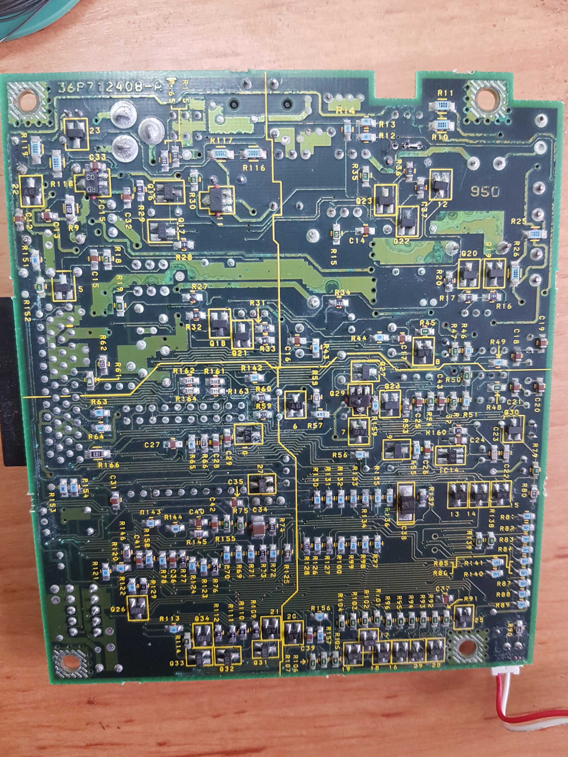
This series of posts is the result of months of work in tracing out the circuit and figuring out what everything is doing. In the end this resulted in a complete schematic for the T1600’s PSU board marked FIVPS2, which I’ll upload to GitHub and/or archive.org somewhere in the coming weeks.
Tracing the PCB
With the introduction out of the way, let’s get to the issues at hand.
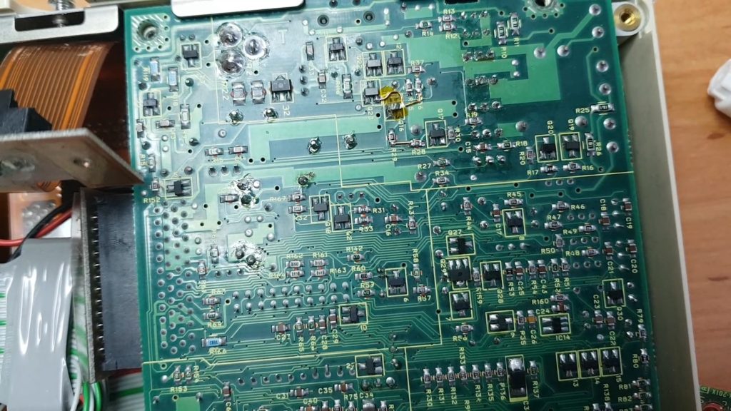
As I stated in my last post, I had cleaned the PSU board and replaced all capacitors but I still didn’t have a working board.
Not knowing how this thing is put together and having no schematics available my only option was to start testing the traces.
All of them.
Tracing every single connection is a monster task.
During the process I had around 100 open tabs in Chrome with datasheets, buck/boost converter theory and U.S. patent applications among others.
As Q29 was completely destroyed and I couldn’t figure out what it should be I reached out to some people on the Vogons forum and the EEVBlog forum to figure out what it was.
Thanks to these forums I was able to figure out that Q29 should most probably be a NPN BJT or N-Channel MOSFET. I also learned that a diode I had drawn probably wasn’t a shottky-type but a zener.
Not having any other boards to check what exact type of component it should be, I started checking EBay for a second machine.
Enter the T1600/40
This lead me to a seller on EBay.de that had a T1600/40 for a reasonable price so I had it shipped to The Netherlands.
This machine was also yellowed, but not nearly as much as the T1600. It was also very dirty and had some BOSCH stickers on it and a BOSCH branded expansion card, leading me to beleive it was used as some kind of industrial control system.
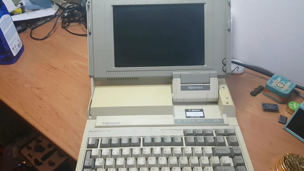
After taking apart this machine it became clear that it was nearly the same, nearly being the operative word.
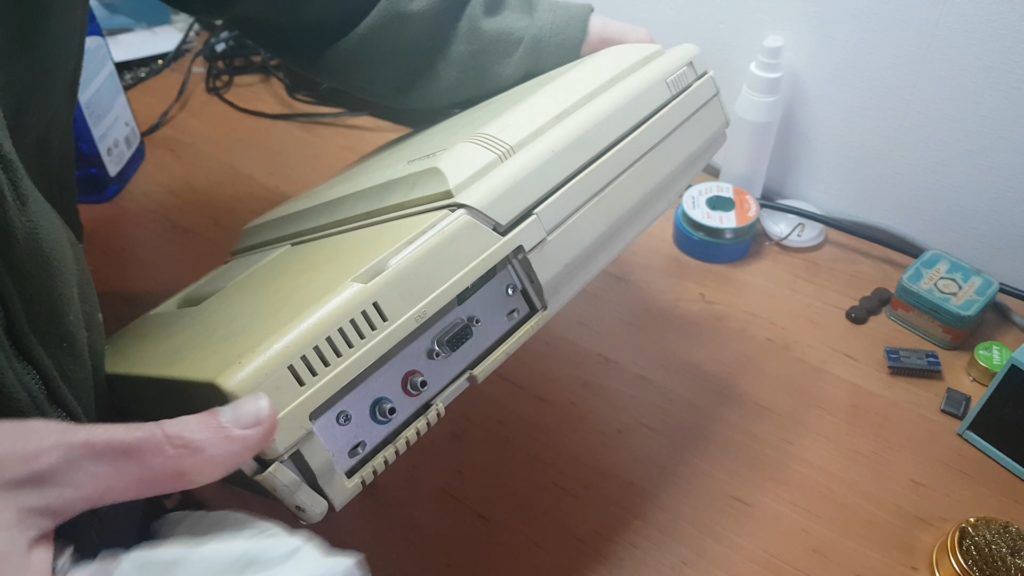
The motherboard is virtually the same but this machine has a 40MB JVC harddrive (hence the “/40” in the model name) using a proprietary 26-pin interface of which very little is known. This also means that the harddrive controller is different.
Let’s check out the PSU
The PSU board on this machine seems to be a newer revision, it is marked FIVPS4 and has some slight differences in component makeup.
Some of the capacitors were combined in single, larger ones.
The 5V regulator for the 5V RAM supply was changed from a surfacemount component to a TO-220 type.
The MOSFET drive transistors and their accompanying resistors are slightly different as well.
This results in the switchmode part of the supply looking a bit different but in general the PSU boards are pretty much the same.
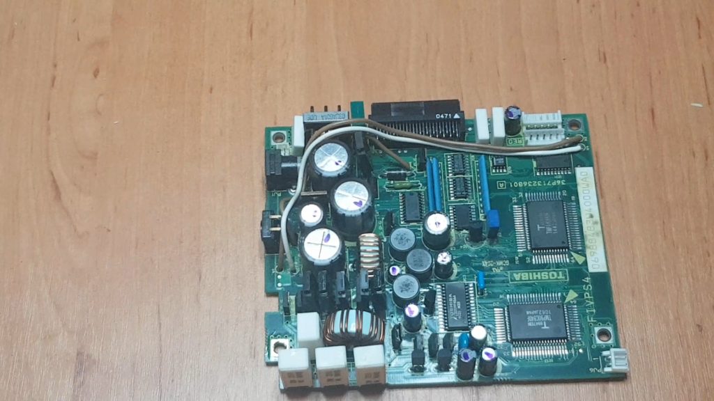
Luckily, Q29 on this board was intact so I was able to verify that it’s a N-channel power MOSFET.
Furthermore, the diode I couldn’t identify turned out to be a 18V Zener.
These were the last two peices of the puzzle and allowed me to complete the schematic.
I replaced all capacitors on this board but unfortunately it too wasn’t working.
Get to fixing things already!
Yeah, yeah I know. It’s a lot of background but that is kind of what this blog is for.
Using my newly created schematic I was able to track down two broken traces on the T1600/40’s PSU board. These weren’t visible by eye, even under magnification but using my multimeter they showed right up.
I patched these with some enameled copper wire and a bit of kapton to prevent shorts.
And it worked!
I had good hopes for this board as it wasn’t nearly as damaged as the FIVPS2 board from the T1600 but this was way simpler than I could have hoped for.
As for the FIVPS2 board, well…. That’s a different story for a different post.