In the previous part on the Toshiba T1600 Power supply board I talked about how I traced the board and identified some of the mistery components on it. I also showed my repair efforts on the T1600/40’s PSU and how it required minimal effort to fix.
As stated at the end of the previous part, The T1600’s FIVPS2 board deserves a post on it’s own, so here it is.
The post after this will go into detail on the PSU and how it works. I will also include some scope traces to show how thing should look.
Testing everything and replacing broken parts
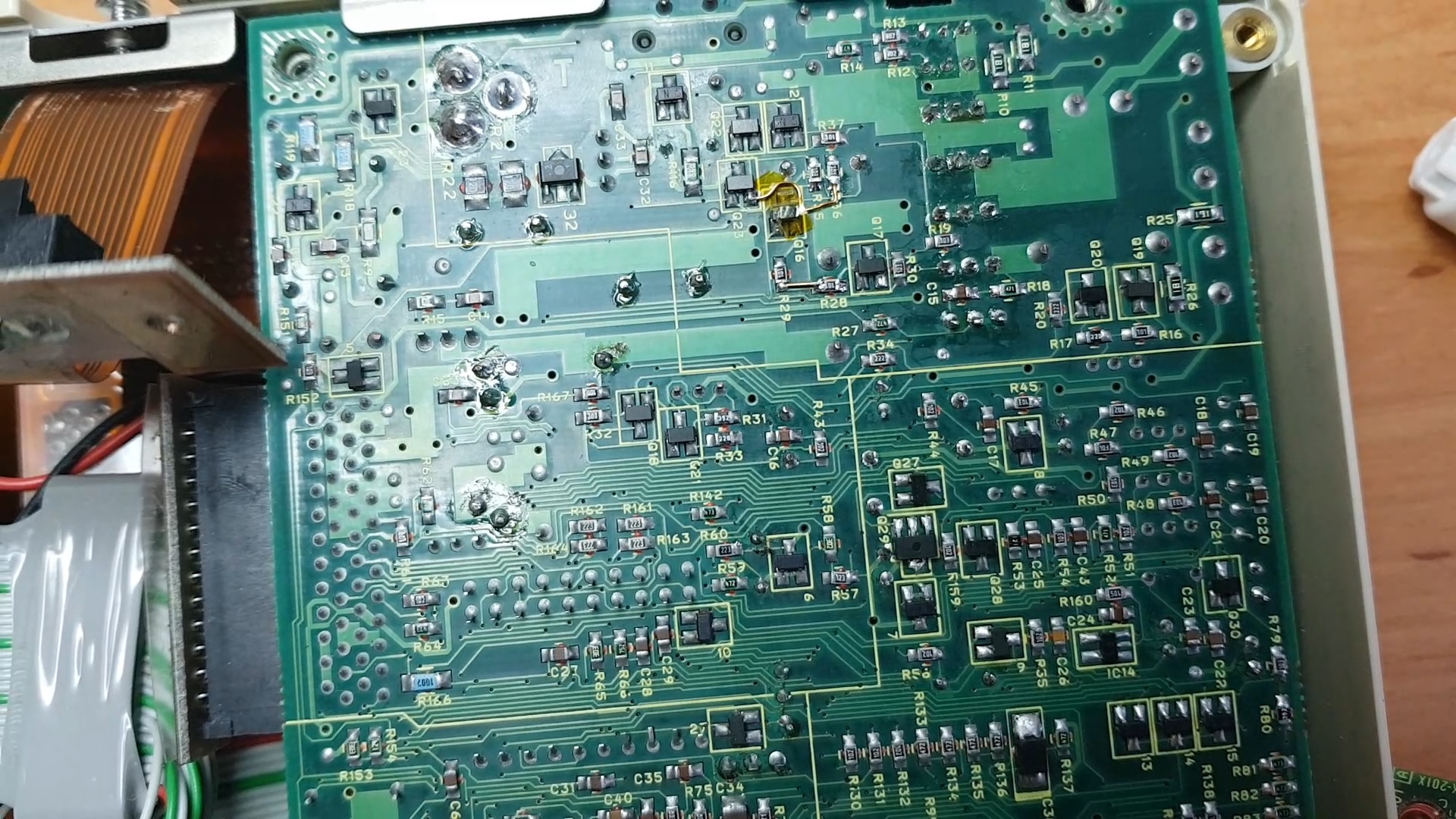
Having traced the entire board and not finding what was wrong with the thing I went and did the next logical thing: testing components.
As I found datasheets and specifications for nearly everything on the board this was quite easy to do.
Having a hot-air soldering station to aid the desoldering of the SMD chips really helps a lot.
I ended up finding IC5 (a uPA1600 Monoliothic Power MOSFET array) to have a defective element, it never managed to turn on or off completely. As this is driving one of the switchmode converters I replaced it with a new one.
I also found IC7 and IC8 (LP324M Quad op-amps) to behave a bit different then they should and replaced these as well. They shouldn’t affect the operation of the PSU in a way that results in this behaviour as these are used for current sensing on the charge circuitry.
After replacing all these ICs with new, tested versions I was still faced with the same symptoms: a blinking DC in LED.
As all I had was a simple 2-channel analog oscilloscope I hacked up a very crude oscilloscope using a Arduino and the built-in serial graph monitor to draw some voltage traces. The results from this lead me to some of the voltage rails that weren’t quite what they should be.
Time for some new toys
Without a proper DSO it was difficult to actually see what it was doing so I finally gave in and purchased a Rigol DS1104Z Plus oscilloscope.
Using my new equipment I quickly traced the problem to the -9V rail which wasn’t being switched at all.
Unfortunatly, I didn’t save any screenshots of the ‘scope at this point to illustrate what was happening.
As the PWM signal was getting to Q5 and it was getting it’s 12V supply this meant replacing Q5 (2SJ133 P-Channel Mosfet) which is the main switching element for this rail.
Next I had a different problem: The -9V rail was switching but nothing got to the output or the capacitor. As can be seen from the partial schematic below the only thing that can be broken at this point is diode “8”
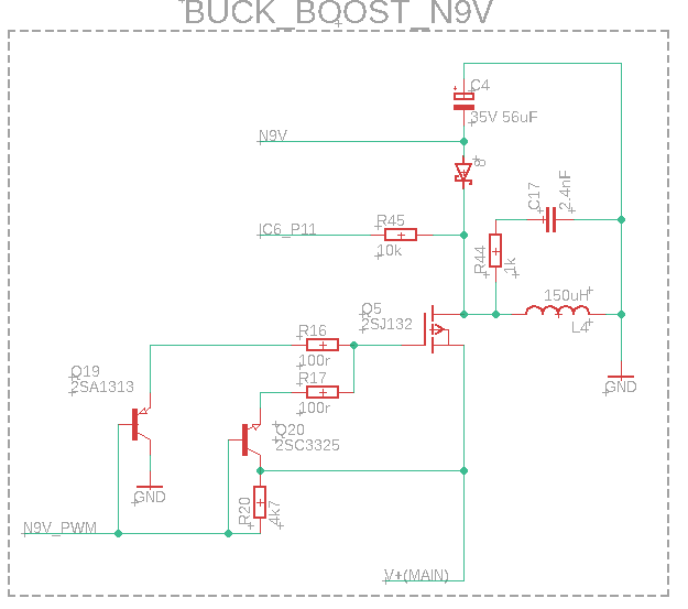
I ordered a replacement diode (BAS16 Fast switching diode) and soldered it in.
After reconnecting the oscilloscope and barreljack I pressed the power button, not expecting anything.
The last little gremlins
To my surprise there was no blinking LED anymore, the board was working!
Time to get that on video. Powered down the board, grabbed my camera and started recording. Skip to the part wher I show that it now works and…. nothing.
After a while I noticed that one of my bodge wires wasn’t making proper contact with the traces so I removed it, cleaned and tinned the traces properly and reconnected the wire.
And that was it, board fixed. Finally.
After a good clean, retrobright and reassembling everything I now have a working T1600 and T1600/40. The T1600’s PSU is not as good as it should be but after a couple of component swaps seems to at least be stable.
Conclusion
I ofcourse shared my success on the Vogons forum and was asked what, in my opinion, are the most common failures.
At the time of posting there I didn’t really know what to answer but after testing and fixin another T1600 PSU from a fellow forum member I can pretty confidently state that the most failure-prone components after the capacitors are the switchmode converter MOSFETs.
The diodes aren’t quite ruled out either though the only failure I’ve seen is on my T1600 PSU and I’m not sure that that’s not my fault.
Unfortunately, some of these MOSFETs are increasingly difficult to obtain. There are 1 or 2 sellers on AliExpress that supply them and as far as I can tell these are legitimate components and work flawlessly. There are also a couple of sellers on EBay but prices on these are pretty high so it doesn’t make sense to just order a complete set and replace all of them as a matter of course.
Equipment-wise I would recommend a decent DSO or at the very least something like my Arduino-scope hackjob to track down which of the MOSFETs are not working.
I would also recommend a cheap Chinese component tester to actually test the MOSFETs after desoldering them.
When you are confident that you’ve identified all the damaged transistors go ahead and order replacements.
When ordering replacement capacitors my advice from the T1000LE repair still holds true: Don’t cheap out on them. Use a quality brand (Panasonic, Rubycon, Würth, etc) 105°C low-ESR capacitors.