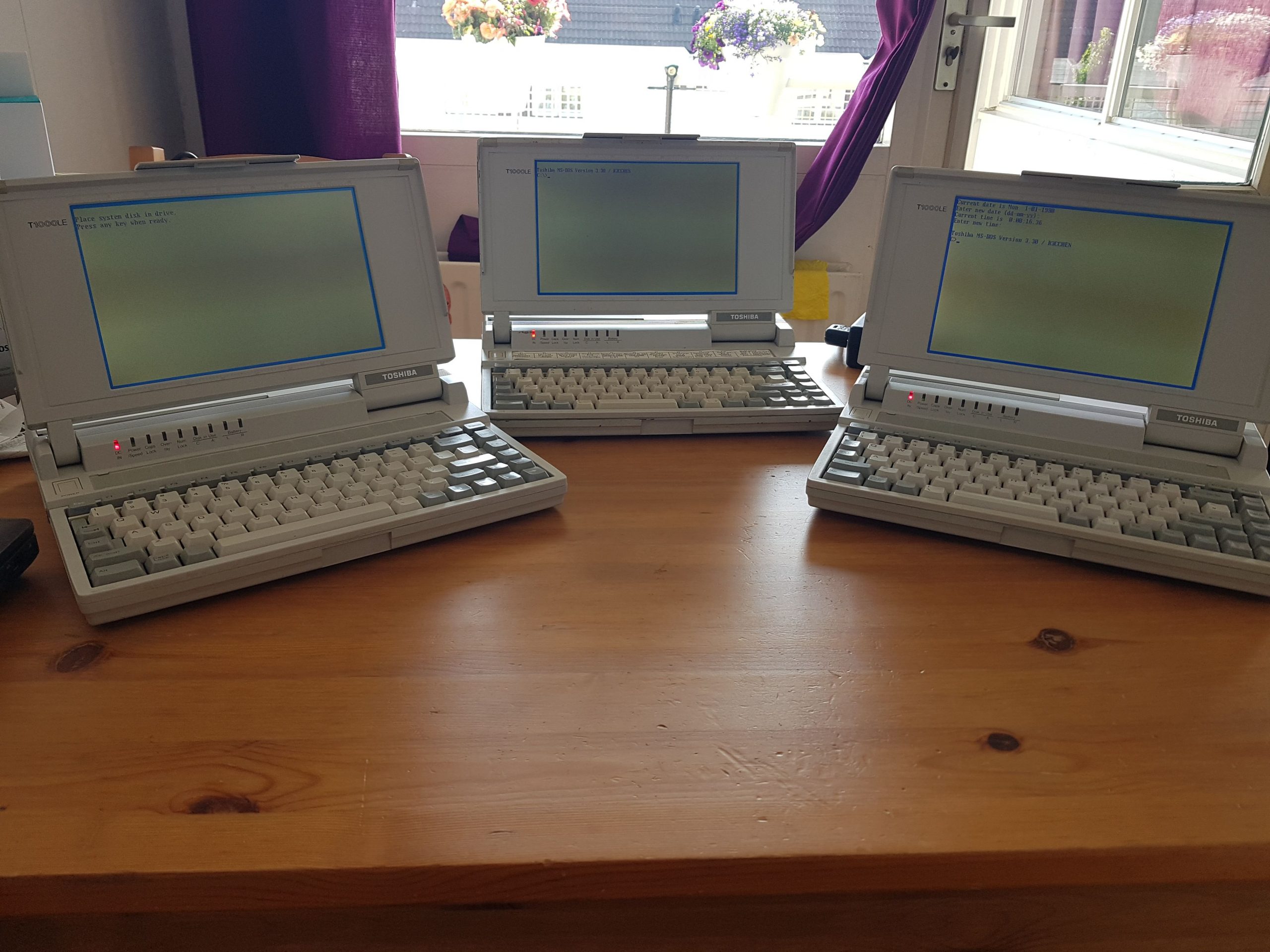
My intention to post weekly updates about the T1000LE PSU debugging hasn’t really worked out as “real life” got in the way a bit. Nevertheless, here is another, hopefully last update about the PSU as I’ve managed to repair all three machines.
As I mentioned in my last post about these machine I started debugging, measuring and scoping out all the signals which is when I noted that some signals on the first machine didn’t correspond to the second and third. In particular, the charging circuitry for the SUB-battery didn’t show any signs of life.
Tracing out the traces
Armed with my (crude, incomplete and probably inaccurate at some points) schematic, a multimeter and soldering station I started checking where things were going wrong.
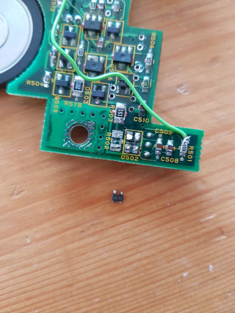
I already had desoldered IC501 on this machine and found a lot of damaged traces and via’s underneath it but had no way to see what should go where.
Also, I managed to snap off one of the legs (pin #8) which, as it turns out, is connected through a small via I couldn’t see through all the corroded junk.
Using the other 2 machines (and a hot-air soldering station instead of my trusty old Weller iron) I traced out everything and found 4 broken traces.
I also desoldered some of the components from the underside of the board so I could clean off any electrolyte residue from underneath them. As you can see, this board was quite damaged.
Repairing the traces and “fixing” the IC
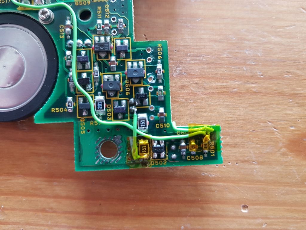
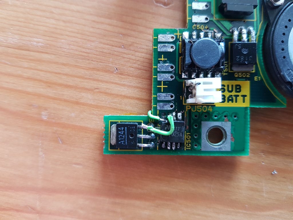
As I now knew where everything should go I cleaned up the board and cut some 0.8mm solid bodgewires to size, soldered them on and taped it down with some kapton tape.
The IC with the missing leg was a bit fiddly but manageable. I grabbed it firmly using some small pliers and used my dremel to grind down a part of the plastic package, revealing about a millimeter of the leg inside the package. That is enough to be able to solder a wire to it.
I placed the IC back on the board and routed some more bodge wires to fix all missing traces and vias, the result is in the below images.
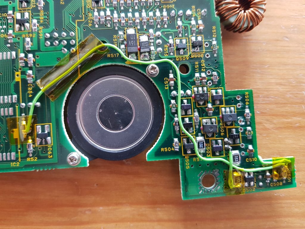
Still not done with the caps
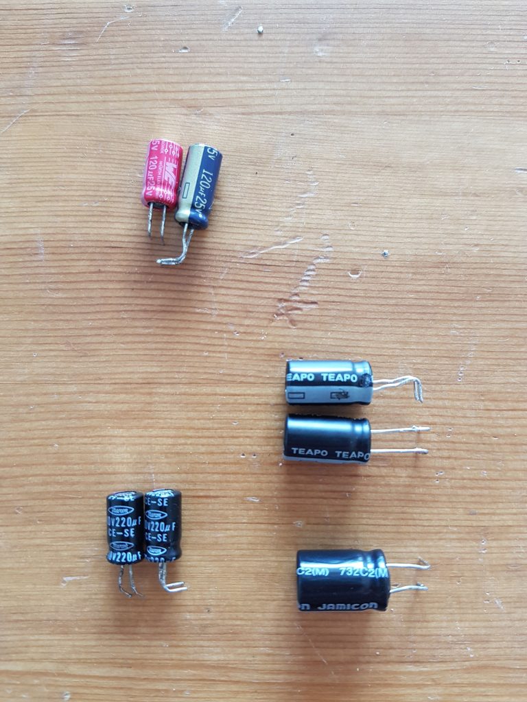
As you can see in the above images the board is missing all of it’s electrolytic capacitors. I actually ordered two sets of capacitors when I ordered the ones for the third machine as I figured cheap caps had something to do with the issues I was having.
I replaced all caps on the PSU section with Würth and Panasonic brand capacitors just to be sure.
The old, cheap Chinese capacitors were all found to be out of spec, even after being used for only a short time. They all had out of spec capacitance and some had a very high ESR for a low-mileage capacitor so these were thrown in the bin.
Putting it all together
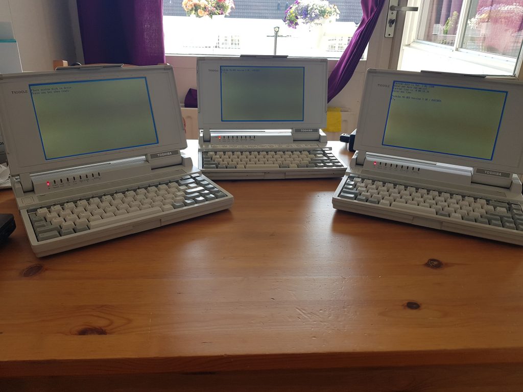
All that was left to do was put everything back in the machine, connect the cables and power it on.
Lo and behold: All three machines now work perfectly fine, bar some floppydrive belt and HDD issues.
T1000LE PSU, the conclusion
So what was wrong with these machines? Well, not that much really. You just have to know what to look for and what to buy as replacement parts.
The first machine I got suffered from brownouts because of the cheap caps degrading quickly, hence it didn’t run in “fast” mode after a couple of hours runtime.
The second machine with the failed Q502 transistor still has some cheaper caps in it and I bet that is the cause of the failure on this one.
The third machine worked perfectly fine immediatly after replacing all the caps.
Tips before buying
These things are fiddly at best and they all have the exact same symptoms.
Unless you are buying a working, recapped machine with working floppydrive you are in for a bit of a project.
To sum it up:
The caps will leak.
Some more than others and depending on how the machine was stored it will leak all over the motherboard and under SMD components.
It eats away at traces and vias so be prepared to do some deep cleaning and grab your tweezers for some small SMD component de-soldering.
The floppydrive belt
These degrade to a chewing gum-like consistency and will immediatly break. Replacements can be found on Ebay but be aware there are sellers who sell sub-spec products that won’t work correctly.
The Conner harddisks
These fail more often than the JVC ones.
Of all the machines I have and have had over the years it’s always the Conners that seize up. The JVC drives work flawlessly and much more silent.
These are the only drives that work
Yes, that’s right. Only Conner-brand disks of 20MB and these exact JVC disks will work. You can not just plug in a different PATA drive or IDE2CF/IDE2SD adapter. Replacements for the Conner drive can be found on some questionable websites for absolutely insane prices.
Use quality components
This seems like a no-brainer but at least for the PSU section you should use brand-name, preferrably low-ESR, 110°C caps.
Stay clear of the cheap(er) Chinese brand, they will simply not work or fail quickly.
Seek help and ask for advice
This one also seems like a no-brainer but there are a lot of websites dedicated to electronics and vintage computers. Ask for help and/or advice there, the community is very helpful when you show you’ve put in some effort to resolve it yourself.
For example check out the VCfed forums and Vogons
That is it, at least for now.
If and when I have some more information on these it will ofcourse be posted here.
In the mean time I still have to clean the mouldy C64 as it has been stinking up my office for long enough. I also expect to receive all the parts for my NetPi-IDE next week so I can start experimenting with that.
Be sure to check back here for more projects, I’ve got quite a few lined up.