Today’s post is about debugging the T1000LE machines, specifically their power supplies.
As I had to wait for some stuff to arrive for my mouldy Commodore 64 I had some time to dig deeper into the mystery that is the T1000LE’s PSU circuitry.
And I went in, deep. I also posted to the Vintage Computer Federation forums as more people are having PSU issues with these machines
Also, the oppertunity arose to buy another (third) T1000LE with similar symptoms as the other 2: Bad/leaky caps preventing the machine from working. It was kept in a suitcase for years so it looked very neat and still had the original manual and even the DOS manual with it so I grabbed it for € 55,-. It seems people are really getting rid of clutter as days later 2 more machines popped up but as I already have 3 I think I will pass on them unless they end up going for cheap.
All-out on the new parts
For this machine I decided to go all-out. I didn’t even try to boot it but instead just started disassembly. (Pictures of what the inside looked will be in a seperate post so be sure to check back here!)
I ordered a set of capacitors, this time choosing only high-end Panasonic caps with the exception of the 120uF 25V ones being from Würth Elektronik.
I thoroughly washed the board using soapy water and Isopropyl Alcohol (IPA), removed the corroded solder and even removed and resoldered a transistor, inductor and 4 SMD components to get rid of all the corrosion.
The debugging continues
This also gave me the oppertunity to (partly) reverse engineer the board to a schematic to make sense of some things. This is not even close to done yet so I won’t show it here as to not cause confusion.
After replacing the capacitors and reassembling the machine it worked like a charm so time to take some measurements. You’ll find them in the pictures below.
All scope traces are 5V/div and 5uS/div, the image captions refer to the first image showing the test points.
Moving forward with the T1000LE
So where to from here? As I have 2 working and 1 sort-of-working machine I think I’ll use the sort-of-working machine to start tracing things out and create a more accurate schematic of the PSU so debugging and testing will be easier in the future. This is quite complicated as the board appears to have at least 4 layers of copper.
As I have boatloads of time because of the lockdown I’ll be debugging the T1000LE further until I can find what it is that causes them to be so fragile.
Check back here, I’ll try to post weekly about this for a couple of weeks at least.

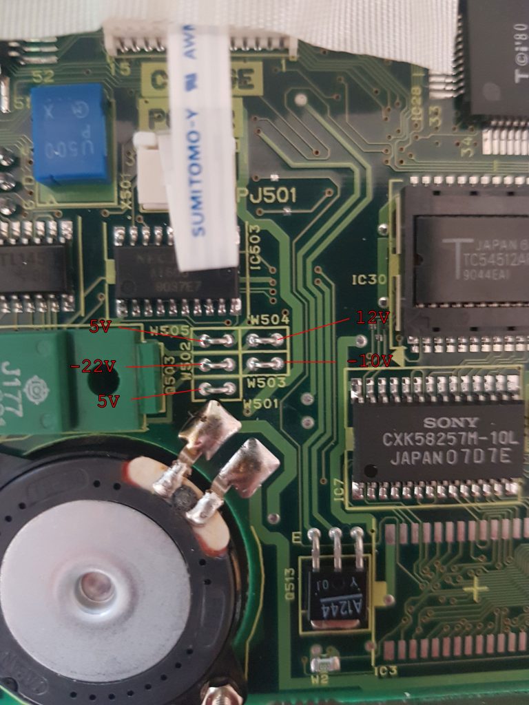
PSU section measurements Wire bridges measurements 
TP1 TP2 TP3 TP4 TP5 TP6
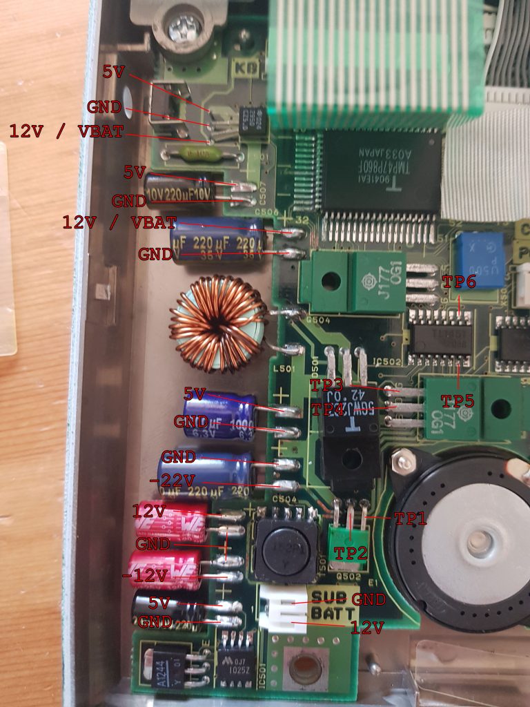
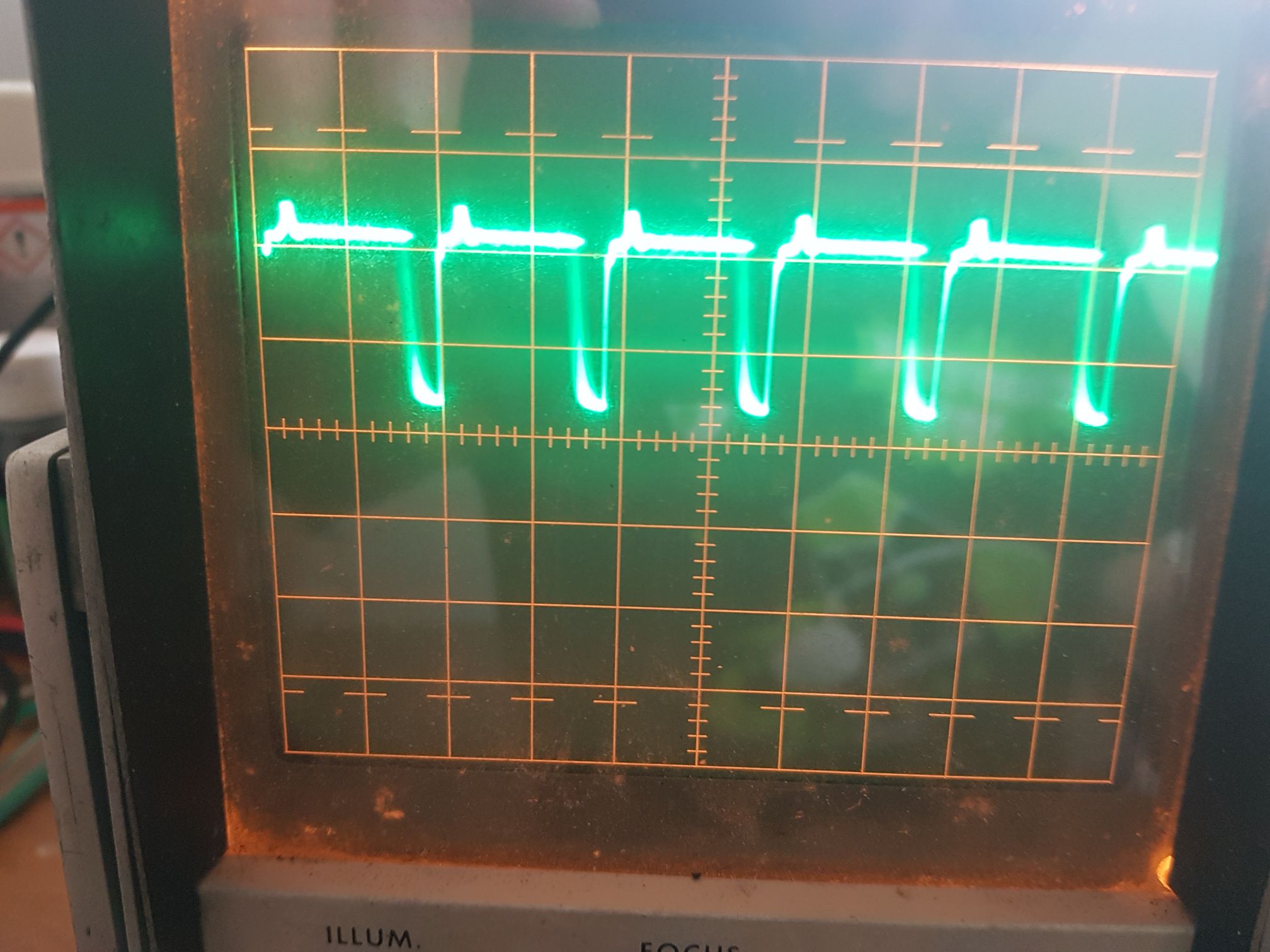
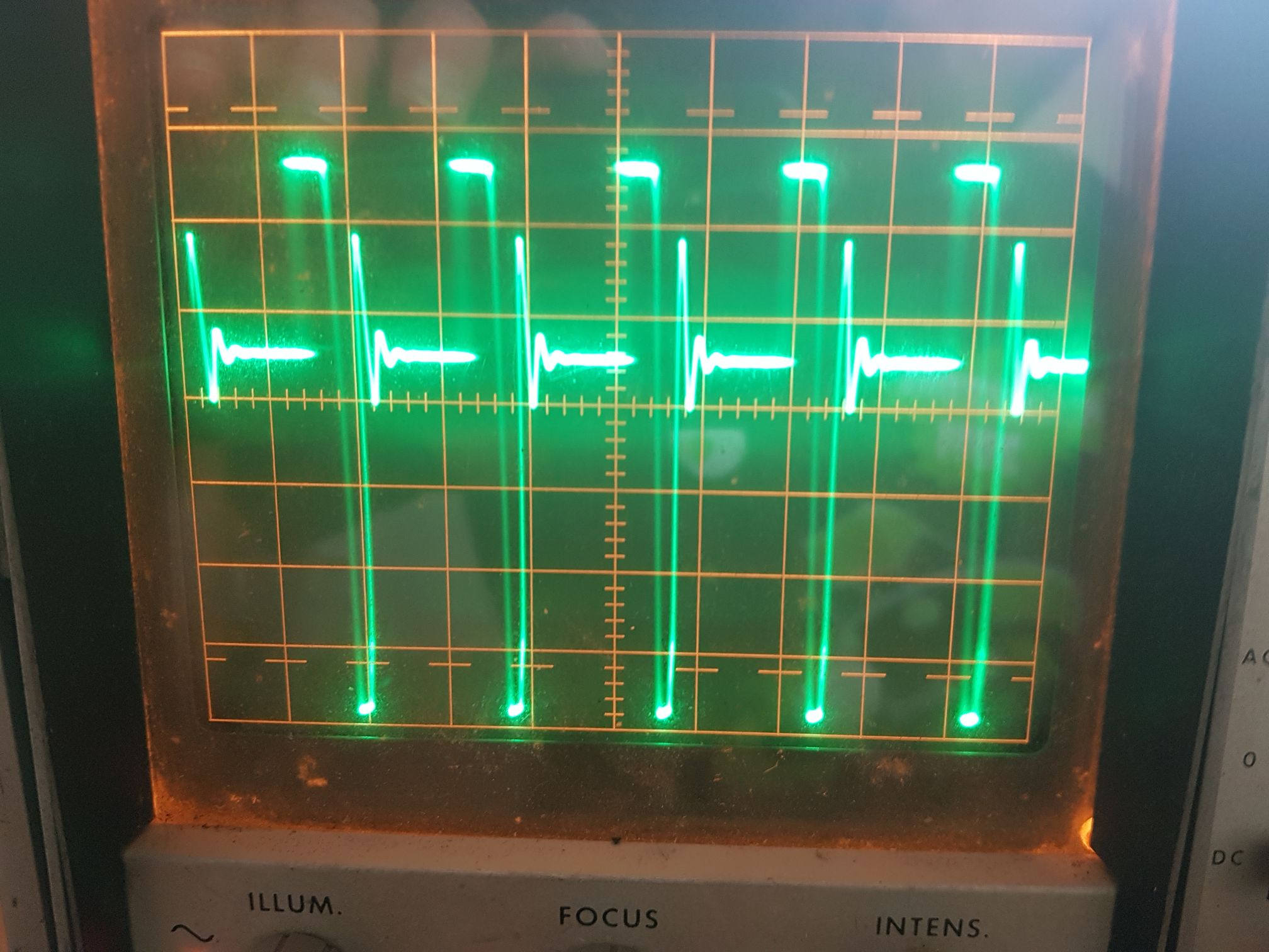

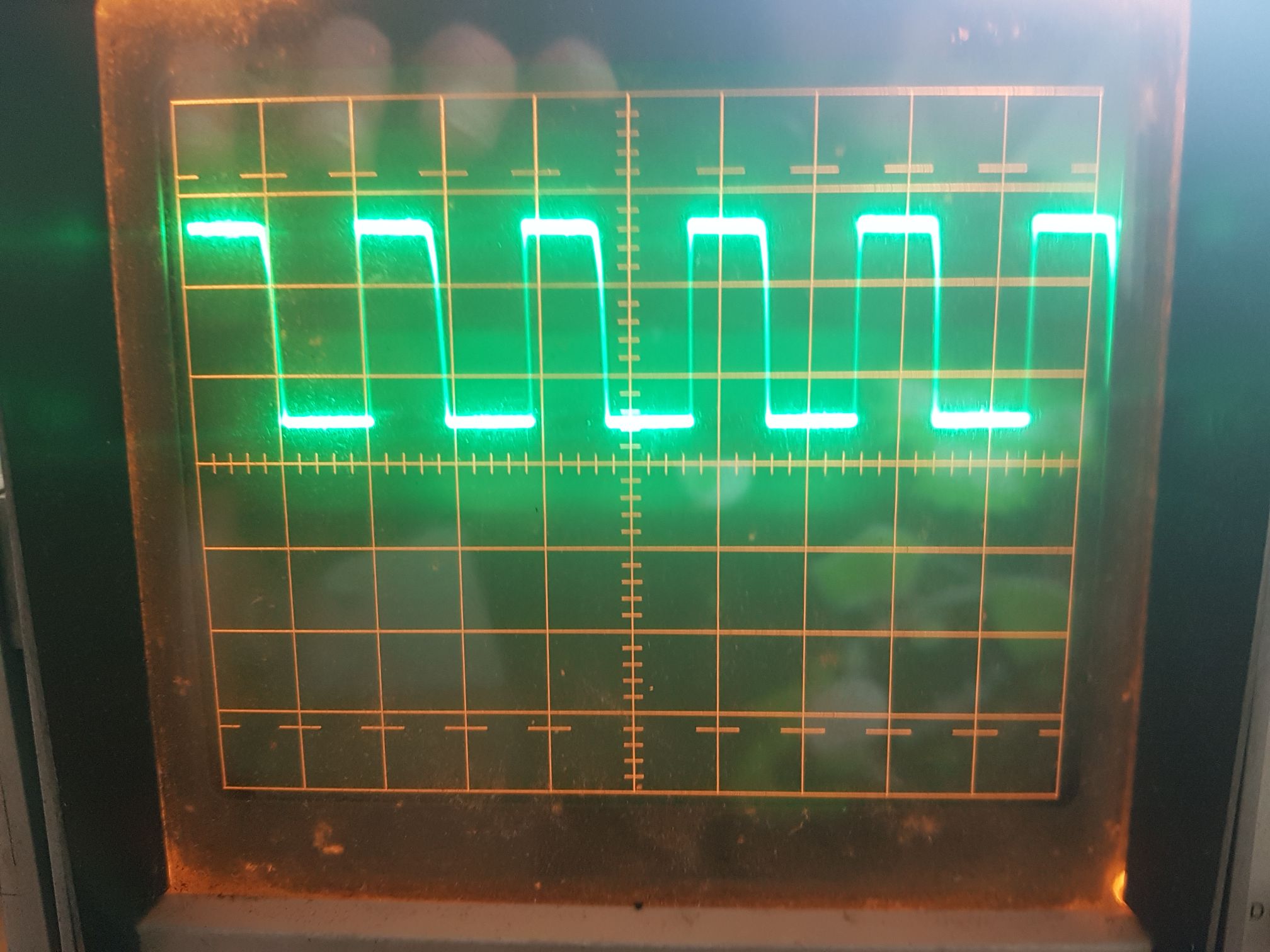
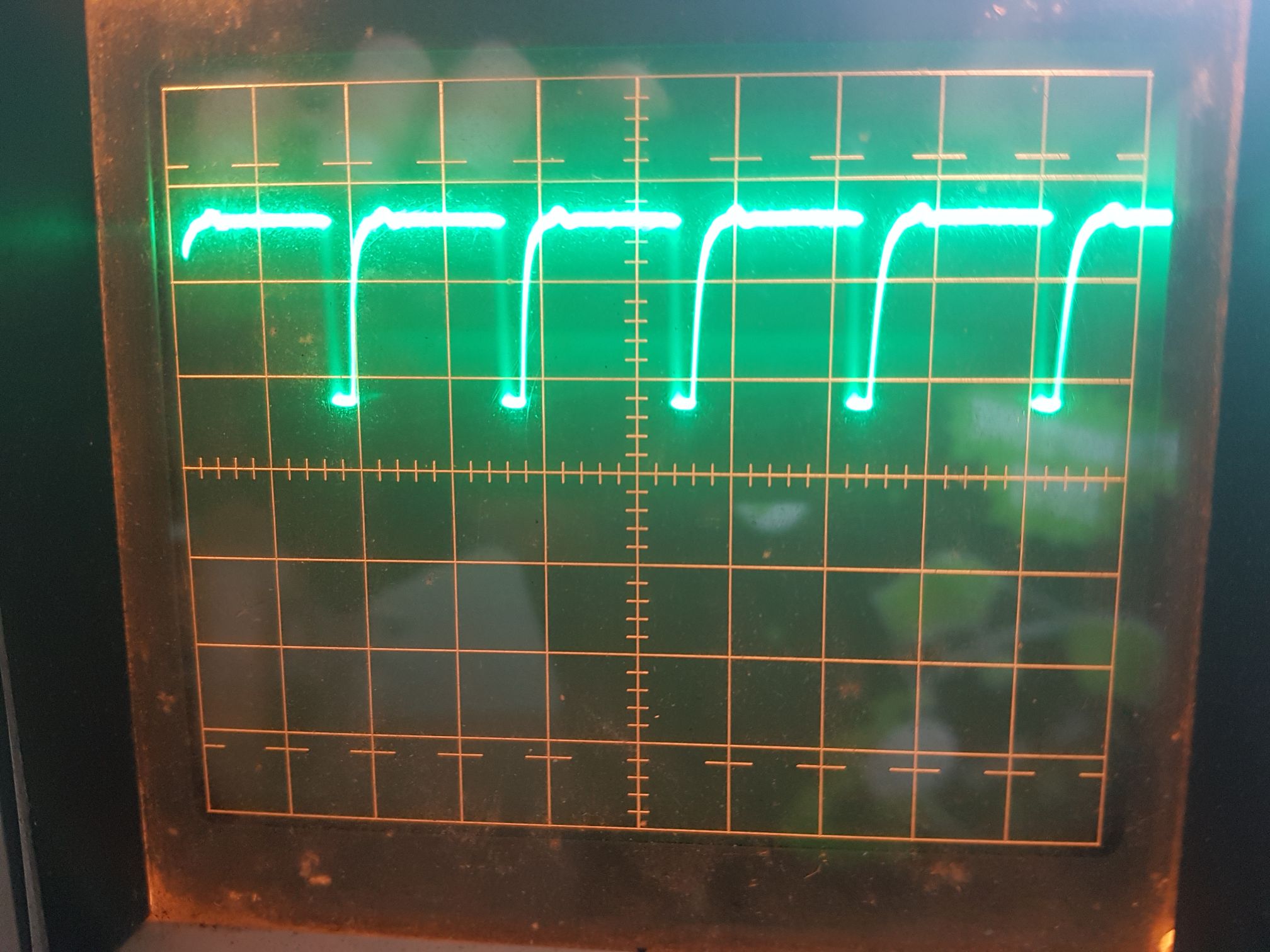

All scope traces are 5V/div and 5uS/div